
netvision LaserTools

netvision LaserTools Weld

From the joint in the CAD model to the collision-checked welding program.

As an offline programming solution netvision LaserTools reduces time consuming teach-in procedures and therefore minimizes waste of valuable machine resources. Laser welding is where that matters most. Seams run along the joint between two parts, and the beam has to follow them at the right angle – on flat assemblies as well as on three-dimensional weldments. netvision LaserTools Weld derives the seam and the beam orientation directly from the CAD model and turns them into a verified NC program.
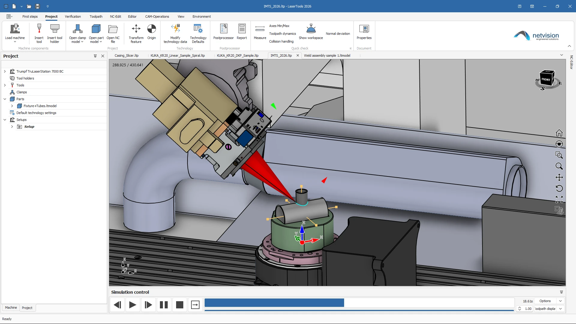
Flexible welding strategies for any part geometry

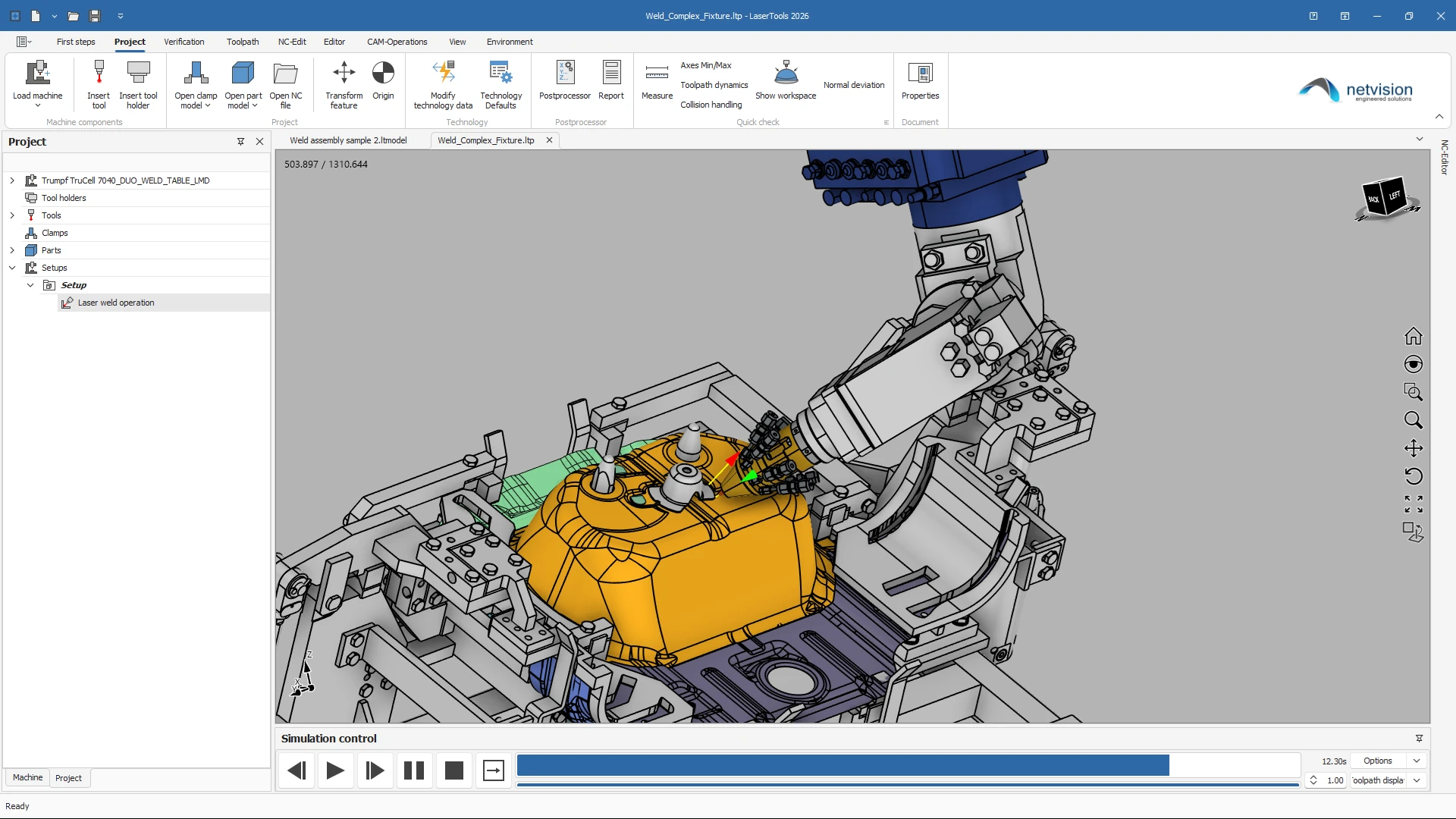
Welding 2D for seams in a working plane, Welding multi-axis for 3+2 and 5-axis seams on three-dimensional assemblies, Spot welding for individual weld points, Offset Slots 2D for oblong seams running parallel to a contour at a defined distance, and Welding Cycles for calling the weld cycles of the control itself. One strategy family covers the whole part instead of forcing every joint into the same scheme.

Beam orientation that follows the joint

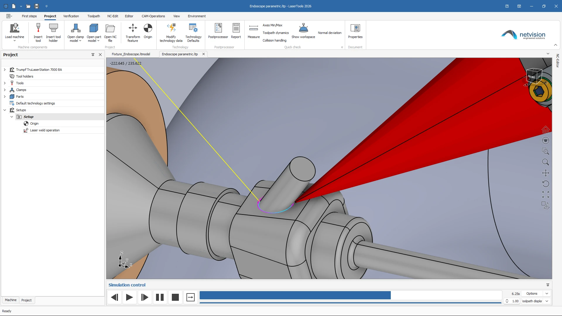
The seam is picked as an edge or a contour on the model; the orientation comes from the adjacent faces, or from the bitangent between them, which the system determines automatically when no faces are selected. Side and advancing angle set the sideways tilt and the lead or lag in the direction of travel, and angular limits keep the orientation inside a defined window – so the programmed attitude is one the machine can actually reach.
Collision-safe programming in the digital twin

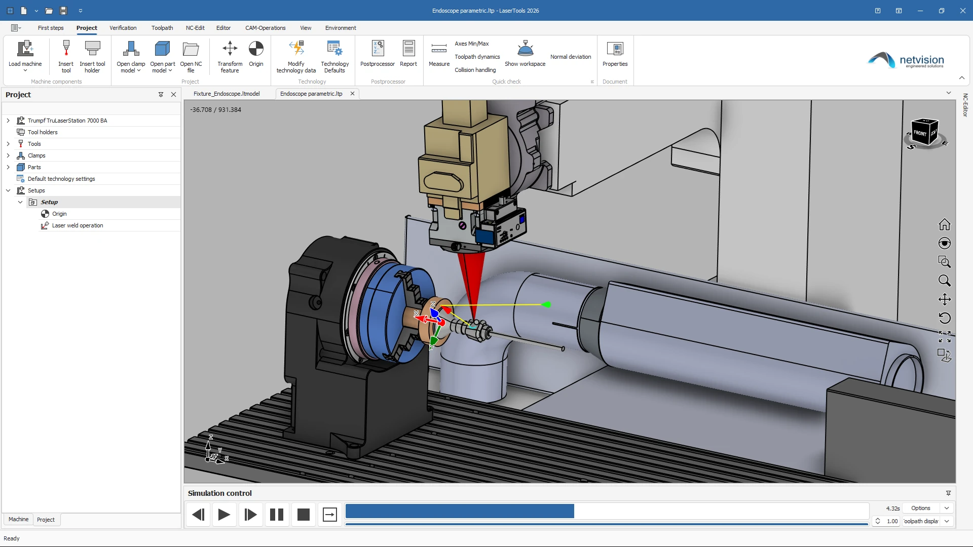
Machine kinematics, welding head, fixtures and clamping are part of the programming environment. Pre-computed collision data keeps the check fast even on large programs, and automatic retraction calculates collision-free linking moves instead of forcing a full retract after every seam. Axis limits, reachability and the accessible machining area are shown on the model, so an out-of-limit position shows up at the programming station and not on the shop floor.
Machine-ready NC output

Post processors for Sinumerik and Trumpf TruLaser Cell controls – Powerline, SolutionLine and Sinumerik One – as well as robot controls deliver code that runs. Analytical arcs are output directly or fitted within a defined tolerance, which reduces the number of NC blocks and smooths the motion on the machine. Technology tables, several technology sets per operation and modifiers on individual moves put power, feed, frequency and ramping exactly where the process needs them – including separate feeds for lead-in, lead-out, linking and safe retraction.

Extend Weld with add-ons

Same project, same CAD kernel, same digital twin.

Features

Everything in netvision LaserTools Weld, at a glance.

netvision LaserTools Weld programs laser welding from the CAD model: seams in a plane, full 5-axis seams on three-dimensional assemblies, spot welds, oblong seams offset from a contour, and calls to the weld cycles of your control. The beam orientation is derived from the joint itself, and every program is verified against the digital twin of the real machine.

Model preparation

  • CAD interoperabilityImport, modification and preparation of models for automated welding
  • Supported file formatsDXF, DWG, STEP, IGES, STL, BREP, IPT, IAM, 3DM
  • Native CAD interfaces (options)SAT, Parasolid, Siemens NX, CATIA V5, Creo, SolidWorks, Rhino, Solid Edge, Inventor and Fusion
  • Integrated modellingSolids, surfaces, meshes and subdivision bodies in one environment
  • Sketching2D and 3D sketches with constraints; DXF and DWG imported straight into a sketch
  • Topology repairMerging of edges, replacement of edges by curves, removal of degenerate faces
  • Joint preparationSplitting and trimming by face, curve or plane
  • Seam extractionDetection of edges, contours and the faces adjacent to them
  • Selection setsReusable contour and face selections across operations
  • Work planes and measuringTrue minimum distances, radius reporting, planes from geometry or points
  • Scan data (Scan module)Point clouds and meshes of as-built assemblies, cleaned, meshed and best-fit aligned
  • Welding 2DSeams in the active working plane, with automatic projection of off-plane edges and orientation taken from a selected planar face
  • Welding multi-axis3+2 and 5-axis seams on three-dimensional assemblies
  • Spot weldingIndividual weld points with the orientation derived from the underlying faces
  • Offset Slots 2DOblong seams parallel to a contour at a defined distance, automatically divided into segments of a maximum length
  • Welding CyclesCalling the weld cycles of the control, including oblong weld cycles with slot length and slot diameter
  • Automatic beam alignmentOrientation from the adjacent faces or from the automatically determined bitangent, with a maximum face distance for imperfect models
  • Axis tilt optionsSide angle and advancing angle for lead and lag control
  • Angular limitsRestriction of the beam orientation to a defined window around a reference frame
  • Seam offsetWelding side and contour offset relative to the picked edge
  • Lead-in and lead-outOrthogonal, tangential and free-angle linear leads, quarter, half and free arcs, with separate lead feeds and mirrored lead side
  • Link controlApproach and retract distances, safe retraction and automatic collision-free linking moves
  • Arc outputDirect use of analytical arcs plus tolerance-controlled arc fitting to G2/G3
  • Technology managementProject-wide default technology, technology tables and several technology sets per operation
  • Move modifiersFeed, acceleration, laser power, frequency, ramping and presets on selected moves, grouped in change sets
  • PatternsLinear and circular patterns of complete operations
  • Toolpath editingTrimming, limiting and manual moves, plus manually created lines and arcs
  • Feedrate optimization (option)Database-driven tuning of feedrates
  • Operation statisticsAxis limits, machining area and reachability visualization
  • Multi-part setupsSeveral parts in one project, each with its own clamping and zero point
  • Digital-twin executionMirroring of realistic NC behaviour utilizing a fully synchronized virtual twin
  • Collision analysisReworked and considerably faster through pre-computed collision data
  • Kinematic flexibilitySwitchable controllers for table or head kinematics and multiple zero points
  • Critical-axis acceleration insightsHighlighting of dynamic load behaviour during motion
  • Operation-to-NC connectivityMaintaining of direct links between machining steps and code
  • Best-fit positioningPart aligning for optimal geometric accuracy
  • Breakpoint-driven analysisEnabling of focused inspection of critical process moments
  • HMI action emulationMirroring of machine-side commands such as fixture operations
  • Subroutine and cycle executionMachine logic reflection for realistic program behaviour
  • NC version controlTracking of program revisions throughout the workflow
  • NC transformation engineAdapting and restructuring of NC programs for new setups
  • Integrated NC editingDirect in-environment code refinement with breakpoints
  • Post processorsSinumerik, Trumpf universal post for Powerline, SolutionLine and Sinumerik One, TruLaser Cell BA/BC and robot controls
  • Orientation modesORIAXES, ORIVECT and ORIPLANE for circular interpolation
  • NC program splittingReliable output of large programs
  • ReportsSetup and program documentation generated from the project

Ready to see netvision LaserTools with your parts?

Book a live demo and we will discuss your requirements individually.