
Add-on

NetVision LaserTools Robotics Module

Laser robot programs from the CAD model instead of teach-in.

Nowhere is teach-in more expensive than on a robot. Every point of a laser path on a three-dimensional part has to be approached, oriented and stored by hand – and repeated for every new variant. NetVision LaserTools Robotics takes the same laser strategies that drive CNC laser machines and applies them to industrial robots, linear tracks and positioners.
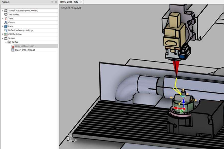
Screenshot placeholder: model preparation in NetVision LaserTools

The complete robot cell as a virtual model

Robot, linear track, rotary tilt positioner, laser head, clamping and part are combined into one kinematic model of the cell. The external axes are part of the kinematic chain rather than an afterthought, so the part is presented to the robot exactly as it will be on the shop floor. Cells are loaded from the machine library or built and adapted with the integrated machine editor.

Robot motion solved and verified before it runs

Tool position and orientation along the laser path are translated into robot joint values by inverse kinematics, with several solver strategies to choose from. The simulation plays the program move by move with the complete cell; collisions of robot links, head, clamping and part are checked on pre-computed collision data, and joint limits, reachability and axis dynamics are shown before the robot moves.
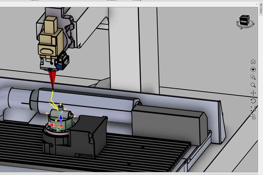
Screenshot placeholder: toolpath planning in NetVision LaserTools

The same laser strategies as on CNC machines

Cutting, welding and deposition operations are programmed on the CAD model exactly as for a CNC laser machine – multi-axis contour cutting, seam welding with beam orientation from the adjacent faces, multi-axis cladding and thin wall build. Side and advancing angle, angular limits and automatic collision resolution keep the tool attitude inside what the robot can reach, and toolpath editing corrects orientations along the path where required.

Robot programs in the native controller language

Post processors write the program in the language of the robot controller: KUKA KRL with .src and .dat files, LIN and PTP motions, approximated positioning and external axes E1 to E3 with laser control via digital outputs; Stäubli VAL3 projects with linear, joint and circular motions; and Cloos robot programs. No manual re-teaching, no transcription of points.

Works with

Same project, same CAD kernel, same digital twin.

Features

Everything in Robotics Module, at a glance.

NetVision LaserTools AddOn Robotics Module brings the laser strategies of CNC machines to industrial robots. Robot, linear track and positioner form one kinematic model of the cell, tool paths are translated into joint values by inverse kinematics and checked for collisions, joint limits and reachability. The result is written in the native language of the robot controller – without manual teach-in.

Robot cell modelling

  • Robot modelsIndustrial robots such as KUKA KR 20 and KR 90 as kinematic models
  • Linear tracksRobot mounted on a linear guide as an additional axis
  • PositionersRotary tilt positioners such as the KUKA DKP-400 in the kinematic chain
  • Machine libraryReady cell models selected from a gallery
  • Machine editorCreation and adaptation of kinematic cell models
  • Collision modelsSeparate simplified collision geometry for fast checks
  • Tools and tool holdersLaser heads inserted from libraries and attached to the robot flange
  • Clamping and partsClamping models and part models opened directly into the cell
  • Multiple zero pointsOrigins placed on part, clamping, positioner or cell
  • Multi-part setupsSeveral parts in one project, each with its own clamping and zero point
  • Laser strategiesCutting, welding and deposition operations programmed on the CAD model
  • Inverse kinematicsJoint values solved from tool position and orientation, with pseudo-inverse and damped least squares Jacobian, FABRIK, gradient descent and Nelder-Mead solvers
  • Tool orientationSide angle, advancing angle and angular limits along the path
  • Orientation alignmentControllers that align the tool with the surface normal or a target point
  • Automatic collision resolutionTool orientation adapted within weighted axis costs
  • Orientation editingAdjust, limit, invert and freeze tool angles along a program
  • Toolpath modificationModify position and orientation, replace or trim sections of a toolpath
  • Path transformationMirror, translate, scale, reverse and morph toolpaths
  • PatternsLinear and circular patterns of complete operations
  • Technology managementProject-wide default technology, technology tables and several technology sets per operation
  • Move modifiersFeed, acceleration, laser power, frequency, ramping and presets on selected moves
  • Cell simulationStart, pause, single step, previous and next move, adjustable speed
  • Collision checkRobot links, head, clamping, positioner and part checked on pre-computed collision data
  • Out-of-bounds highlightingJoint positions beyond their limits marked on the toolpath
  • Axes min/maxJoint ranges of the complete program at a glance
  • Reachable workspaceReachability envelope of the robot shown on the model
  • Toolpath dynamicsVelocity, acceleration and jerk of the robot joints along the program
  • Smooth motionNo axis flips, correct interpolation of moves with large axis angle differences
  • Material depositionAdditive build-up simulated as real geometry
  • KUKA KRL.src and .dat programs, LIN and PTP motions, approximated positioning, external axes E1 to E3, laser control via digital outputs
  • Stäubli VAL3Project, data and program files with movel, movej and movec
  • CloosRobot programs for Cloos welding robot controls
  • ReportsSetup and program documentation generated from the project

Ready to see LaserTools on your parts?

Book a live demo – online or at your machine.