
NetVision LaserTools

NetVision LaserTools Machine Simulation

Test the program on the virtual machine, not on the real one.

Every minute a program is tested on the real machine is a minute the machine does not produce – and every collision found there is expensive. NetVision LaserTools Machine Simulation moves that work to the programming station: NC programs run on a kinematic model of the real machine, with tools, clamping and part, and are checked and corrected before they are released.
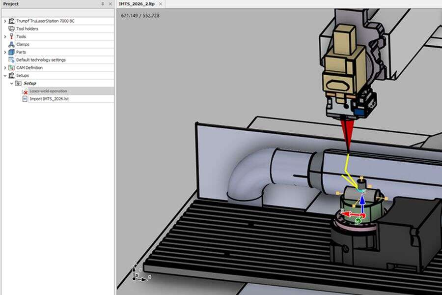
Screenshot placeholder: model preparation in NetVision LaserTools

The real machine as a virtual model

Machines are loaded from a machine library or built with the integrated machine editor, including linear and rotary axes, laser heads with B/C kinematics, rotary tables, slave axes and industrial robots solved by inverse kinematics. Tools, tool holders, clamping models and parts are placed in the machine, and the program runs relative to the same zero points as on the shop floor.

Every move verified before it runs

The simulation plays the program move by move, at adjustable speed or in single steps. Collisions between machine, head, clamping and part are checked on pre-computed collision data, axis positions beyond their limits are highlighted, and the axis ranges of the whole program are reported at a glance. The reachable workspace of the machine is shown on the model, so a part that is placed out of reach is noticed before the first move.
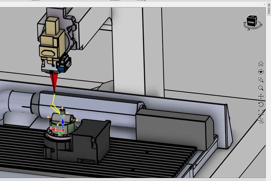
Screenshot placeholder: toolpath planning in NetVision LaserTools

NC programs from any source, linked to their motion

Programs created in LaserTools and programs from other systems are loaded into the same environment. Every move in the simulation knows the NC block it came from, and the integrated NC editor adds syntax highlighting, breakpoints, renumbering, text templates, search and replace. Stopping at a critical block, inspecting the machine state and changing the code happens in one place.

Corrected at the programming station, not at the machine

Problems found in the simulation are fixed where they are found. Tool orientations are adjusted, limited, inverted or frozen along a program; paths are mirrored, translated, scaled, reversed or morphed onto new geometry; linear moves are fitted into arcs and filtered. Collisions can be resolved automatically by adapting the orientation within weighted axis costs – and a report documents setup and program for the machine operator.

Extend Machine Simulation with add-ons

Same project, same CAD kernel, same digital twin.

Features

Everything in Machine Simulation, at a glance.

NetVision LaserTools Machine Simulation runs NC programs on a kinematic model of the real machine, with tools, clamping and part. Every move is linked to its NC block and checked for collisions and axis limits. Problems are corrected where they are found – orientations, paths and arcs are edited in place – before the program is released to the shop floor.

Virtual machine environment

  • Machine libraryReady machine models selected from a gallery
  • Machine editorCreation and adaptation of kinematic machine models
  • Kinematic controllersDirect axes, B/C laser heads, normal and point alignment, slave axes
  • Robot kinematicsInverse kinematics for industrial robots with several solver strategies
  • Switchable controllersTable or head kinematics within one project
  • Multiple zero pointsOrigins placed on part, clamping or machine
  • Tools and tool holdersInserted from libraries and attached to the machine
  • Clamping and partsClamping models and part models opened directly into the setup
  • Multi-part setupsSeveral parts in one project, each with its own clamping and zero point
  • Machine axes panelCurrent axis values of the machine at every position
  • Units everywhereAll inputs, limits and step sizes follow the document unit, millimetre or inch
  • Simulation controlStart, pause, stop and reset, previous and next move, adjustable speed
  • Single step modeMove-by-move inspection of critical program sections
  • Toolpath displayActive move highlighted, leading and trailing toolpaths shown as required
  • Collision checkMachine, head, clamping and part checked on pre-computed collision data
  • Automatic collision resolutionTool orientation adapted within weighted axis costs
  • Out-of-bounds highlightingAxis positions beyond the machine limits marked on the toolpath
  • Axes min/maxAxis ranges of the complete program at a glance
  • Reachable workspaceReachability envelope of the machine shown on the model
  • Normal deviationCheck of the tool orientation against the surface normal
  • Toolpath dynamicsVelocity, acceleration and jerk of the machine axes along the program
  • Smooth motionNo axis flips, correct interpolation of moves with large axis angle differences
  • Material depositionAdditive build-up simulated as real geometry
  • Toolpath normalsDisplay of programmed and interpolated tool orientations
  • MeasuringDistances directly in the simulation scene
  • NC program importPrograms from LaserTools and from other systems loaded into the virtual machine
  • Operation-to-NC connectivityEvery simulated move linked to the NC block it was parsed from
  • Integrated NC editorSyntax highlighting, cut, copy, paste, undo and redo
  • BreakpointsStops in the NC program with margin display and management
  • Program toolsRenumbering, removal of line numbers, text templates, search and replace
  • Orientation editingAdjust, limit, invert and freeze tool angles along a program
  • Path transformationMirror, translate, scale and reverse toolpaths
  • Toolpath morphingTransfer of existing paths onto new geometry
  • Arc fit (CIP)Conversion of linear moves into circular arcs within a tolerance
  • Toolpath filterReduction of redundant moves
  • Toolpath modificationModify position and orientation, replace or trim sections of a toolpath
  • Micro jointsPlacement of micro joints on cutting paths
  • Technology dataModification of technology data and project defaults on existing moves
  • Feedrate optimization (option)Database-driven tuning of feedrates
  • Post processorsSinumerik, Trumpf universal post for Powerline, SolutionLine and Sinumerik One, TruLaser Cell BA/BC and robot controls
  • NC program splittingReliable output of large programs
  • ReportsSetup and program documentation generated from the project

Ready to see LaserTools on your parts?

Book a live demo – online or at your machine.