
Add-on

NetVision LaserTools Blade Repair

From the scan of the worn blade to the verified deposition program.

Blade tip repair shows why that matters. No two worn blades are alike, the nominal model describes the blade as it was built rather than as it comes back from service, and the new material has to follow a thin, twisted profile exactly. NetVision LaserTools takes the repair from the scan of the worn blade to the verified deposition program in one environment.
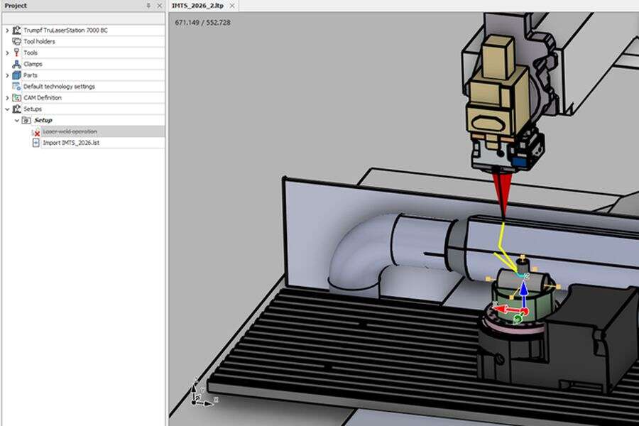
Screenshot placeholder: model preparation in NetVision LaserTools

The worn blade, captured on the machine

A laser profile scanner on the machine records the blade in its clamping, and every profile is placed with the full machine kinematics into the coordinate system of the part. The point cloud is cleaned of outliers and noise without rounding off the thin edges, meshed and aligned to the nominal model by best fit – restricted to the undamaged faces if required. Scanning and repair happen in the same setup, so no re-alignment error creeps in between the two.

The repair zone defined on the real geometry

The damaged tip is cut back along the blade itself: the split is placed at a defined distance along the medial curve of the tip face, measured from a reference axis and turned perpendicular to the blade profile. Meshes are repaired, holes are closed and CAD surfaces are rebuilt from the scan where the nominal model no longer fits. What remains is a clean base for the build-up – on this blade, not on an idealised one.
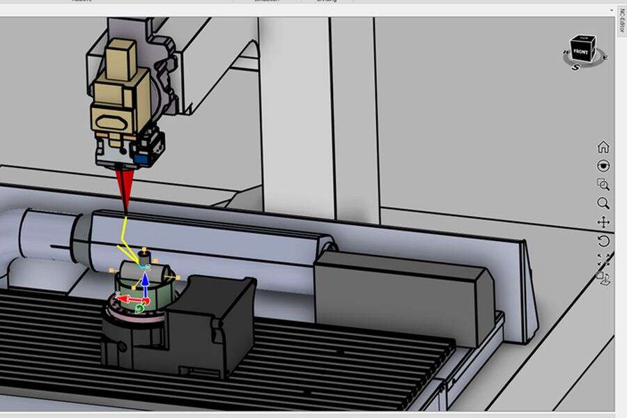
Screenshot placeholder: toolpath planning in NetVision LaserTools

Deposition strategies made for thin blade profiles

Medial path deposits along the centre line of the blade profile, thin wall build creates single-bead walls from constant offsets, and multi-axis cladding and geodesic offsets cover wider sections along the surface itself. A dedicated BLISK build strategy and circular patterns repeat the repair across a complete rotor. Operations are parametric and recalculate when the geometry changes, and saved default parameters and project-wide technology make every blade start from proven values.

Build-up and machine verified before the first bead

The programmed deposition is simulated as real geometry, layer by layer, so gaps, overlaps and unreachable regions of the tip become visible at the programming station. The program runs on the digital twin of the machine with nozzle, head, clamping and blade; collisions, axis limits and reachability are checked move by move, and every move stays linked to its NC block in the integrated editor – so a correction is made and re-checked in the same place.

Works with

Same project, same CAD kernel, same digital twin.

Features

Everything in Blade Repair, at a glance.

NetVision LaserTools Add On Blade Repair scans the worn blade on the machine, aligns it to the nominal model and cuts the damaged tip back along the blade profile. Medial path, thin wall and multi-axis strategies rebuild the tip, the build-up is simulated as real geometry, and the program is verified on the digital twin of the machine before the first bead is deposited.

Model preparation

  • In-machine scanning (Scan module)Laser profile scanner on the machine, machine positions read from the control via Trumpf RCI or OPC UA
  • Kinematics-aware placementEvery profile evaluated with the machine kinematics and placed in the part origin
  • Noise reductionEdge-preserving removal of outliers and flying spots, bilateral smoothing
  • Point reduction and splittingVoxel-based reduction, separation of the cloud into individual objects
  • Point-cloud to meshTriangulation with automatic or manual radius, remeshing and smoothing
  • Mesh repairAutomated repair, closing of gaps and holes, splitting and merging
  • Scan-to-nominal alignment (Best fit)Alignment restricted to selected faces, constraint axis and carried-along bodies
  • Surface reconstructionNURBS patches fitted to meshes and point clouds, recognition of planes, cylinders and fillets
  • SubD reconstructionSmooth free-form surfaces rebuilt from the scan mesh within a defined tolerance
  • Blade tip cut-backSplit along the medial curve at a defined distance from a reference axis
  • Blade loftBlade bodies built from a profile with height, inner and outer radius
  • CAD interoperabilitySupported file formats: DXF, DWG, STEP, IGES, STL, BREP, IPT, IAM, 3DM
  • Native CAD interfaces (options)SAT, Parasolid, Siemens NX, CATIA V5, Creo, SolidWorks, Rhino, Solid Edge, Inventor and Fusion
  • Medial pathDeposition along the medial curve of the blade profile
  • Thin wall buildSingle-bead walls from constant offsets
  • BLISK buildDedicated strategy for blade and BLISK geometry
  • Multi-Axis claddingOffsetting of a curve across the selected surfaces, nozzle kept normal to the surface
  • Geodesic offsetsTrue offsets along the surface, multi-threaded for large parts
  • Offset controlAutomatic or defined pass count, stepover, boundary offset, initial surface offset, path extension and cavity trimming
  • Machining orderTo or from contour, alternating per layer, offset to one or both sides
  • Planar build (slicer)Layer height, contour and infill passes, fill angle increment per layer
  • Multi-axis deposition3+2 and 5 axis strategies with side and advancing angle and angular limits
  • Circular patternsRepetition of complete repair operations across all blades of a rotor
  • Parametric operationsToolpaths recalculated when geometry or parameters change
  • Saved default parametersProven operation settings stored and reused for the next blade
  • Technology managementProject-wide default technology, technology tables and several technology sets per operation
  • Move modifiersFeed, acceleration, laser power, frequency, ramping and presets on selected moves
  • Feedrate optimization (option)Database-driven tuning of feedrates
  • Deposition process simulationRecreation of the additive build-up as real geometry, layer by layer
  • Digital-twin executionProgram run on the kinematic model of the machine with nozzle, head, clamping and blade
  • Collision analysisChecked move by move on pre-computed collision data
  • Automatic collision resolutionNozzle orientation adapted within weighted axis costs
  • Axis limits and reachabilityOut-of-bounds highlighting, axes min/max and reachable workspace
  • Normal deviationCheck of the nozzle orientation against the surface normal
  • Critical-axis acceleration insightsVelocity, acceleration and jerk of the machine axes
  • Simulation controlStart, pause, single step, previous and next move, adjustable speed
  • Operation-to-NC connectivityEvery simulated move linked to the NC block it was parsed from
  • Integrated NC editingSyntax highlighting, breakpoints, renumbering, search and replace
  • NC program editingAdjust, limit, invert and freeze angles; arc fit and toolpath filter
  • Post processorsSinumerik, Trumpf universal post for Powerline, SolutionLine and Sinumerik One, TruLaser Cell BA/BC and robot controls
  • ReportsSetup and program documentation generated from the project

Ready to see LaserTools on your parts?

Book a live demo – online or at your machine.