
Add-on

NetVision LaserTools Scan Module

Capture the real part on the machine and program on what is actually there.

The nominal CAD model is not always the part on the table. Worn components, formed parts and clamped assemblies deviate from it – and the program has to fit the real geometry. NetVision LaserTools AddOn Scan Module captures that geometry directly on the machine and brings it into the same environment in which the toolpaths are created.
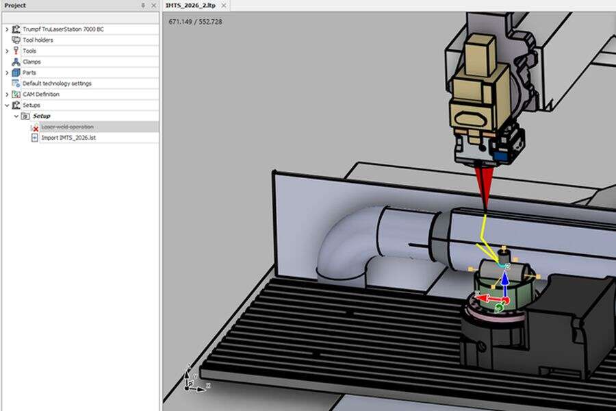
Screenshot placeholder: model preparation in NetVision LaserTools

Scanning directly on the machine

A laser profile scanner mounted on the machine records the part while the machine moves it. The machine positions are read from the control at the same time, so every profile is placed with the full machine kinematics – table-side and head-side axes included – into the coordinate system of the part. No separate measuring station, no manual re-alignment between scanning and machining.

Scan paths planned like any other operation

Scan lines are defined in the virtual machine: start and end positions are set with the tool centre point manipulator, pre-scan and post-scan lengths make sure the whole region is covered, and the scanned area is shown on the model before the scan runs. Scan feed and linking moves are parameters, and the scan program is simulated and collision-checked together with the rest of the job.
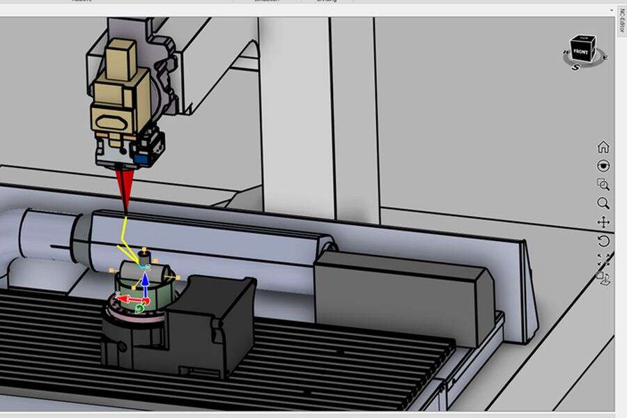
Screenshot placeholder: toolpath planning in NetVision LaserTools

From raw points to clean data

Scan data is cleaned where it is captured: outliers and flying spots are removed, noise is smoothed without rounding off edges, and the point count is reduced to what the task needs. Clouds are split into separate objects, cut back to the region of interest, merged and turned into meshes – all as steps in the model tree that can be changed and recalculated.

From scan to nominal and to new surfaces

Best-fit alignment brings the scan and the nominal model together, restricted to the faces that really matter if required. Planes, cylinders and fillets are recognised in the cloud and rebuilt as CAD surfaces, free-form regions are fitted with NURBS patches. The result is geometry that cutting, welding and deposition strategies accept directly – the basis for repair on the actual part.

Works with

Same project, same CAD kernel, same digital twin.

Features

Everything in Scan Module, at a glance.

NetVision LaserTools AddOn Scan Module records the part directly on the machine with a laser profile scanner and places every profile with the full machine kinematics. Scan paths are planned and simulated like any other operation. The cloud is cleaned, aligned to the nominal model and rebuilt into CAD surfaces that cutting, welding and deposition strategies use directly.

Scan acquisition

  • In-machine scanningLaser profile scanner on the machine, profiles recorded during the scan move
  • Machine coordinate transferScan start and end positions read from the control via Trumpf RCI or OPC UA
  • Kinematics-aware placementEvery profile evaluated with the machine kinematics and placed in the part origin
  • Configurable axis mappingStandard and extended coordinate sets, adjustable to the axis layout of the NC program
  • Scanner settingsConnection, scan rate, sample step and feed set directly in LaserTools
  • Scan managementSeveral scans per session, saved, reloaded and reprocessed later
  • RescanNew scan started straight from the context menu of the CAM tree
  • Scan operationScan lines with start and end positions taught by the tool centre point manipulator
  • Scan coveragePre-scan and post-scan length, scan area preview on the model
  • Linking movesRapid or feed connection moves, optional retraction, simulated and collision-checked
  • NC program as point cloudTraversed positions of an existing NC program read in as a point cloud
  • Noise reductionEdge-preserving removal of outliers and flying spots, bilateral smoothing, automatic or manual noise level
  • Point reductionVoxel-based reduction with a defined tolerance, also on several clouds at once
  • Split disjointSeparation of a cloud into individual objects by gap width, with small clusters discarded as scanner noise
  • Edit point cloudCutting back by plane, one-sided or symmetrical, with stable selection handling
  • Merge point cloudsCombination of several scans into one cloud
  • Manual point cloudCreation of a cloud from picked points
  • SnappingPicking of cloud and mesh points during all selections
  • Mesh from point cloudTriangulation with automatic or manual radius
  • Mesh to point cloudConversion of meshes for comparison and alignment
  • Shrink wrapElastic wrapping of a cloud onto a Brep or mesh, with adjustable stiffness and gap bridging
  • Mesh processingRemeshing, closing gaps, smoothing, splitting, merging, offset and autorepair
  • Point cloud exportHand-over of cleaned clouds to other systems
  • Best fitAlignment of scan and nominal geometry, restricted to selected faces on either side if required, with further bodies carried along
  • Reliable on flat partsReworked best fit for point clouds and points picked in any order
  • Feature recognitionDetection of planes, cylinders and fillets in a cloud, output as trimmed NURBS bodies with RMS fit tolerance
  • Patches from mesh or cloudNURBS surface fitting on meshes and point clouds
  • SubD reconstructionCoarse control cage fitted to a scanned mesh within a defined tolerance
  • MeasuringTrue minimum distances between scan, mesh and CAD geometry
  • Work planes on meshesPlanes from three points picked on a scan mesh
  • Scan-to-pathRecognised and fitted geometry used directly for cutting, welding and deposition toolpaths

Ready to see LaserTools on your parts?

Book a live demo – online or at your machine.